Recommendation for individuals using a screenreader: please set your punctuation settings to "most."
Descriptive Statements:
- Analyze electrostatic phenomena and properties of various charge distributions (e.g., behavior of electroscopes, polarization by induction, charging by friction).
- Apply knowledge of electric field lines and forces to various simple charge distributions (e.g., point charges, electric dipoles, line charge), including solving problems.
- Analyze the motion of charged particles in uniform electric fields in one or two dimensions.
- Demonstrate knowledge of potential energy and electric potential difference for various simple charge distributions (e.g., point charges, electric dipoles, line charge).
- Demonstrate knowledge of scientific and engineering practices, crosscutting concepts, safety procedures and the proper use of equipment, and the engineering design process related to electric charge, electric fields, and electric potential.
Sample Item:
A rubber rod is given a negative charge by rubbing it with a wool cloth. Which of the following statements describes the physical process for this phenomenon?
- Protons transfer from the rod to the cloth.
- Electrons transfer from the cloth to the rod.
- Protons transfer from the cloth to the rod.
- Electrons transfer from the rod to the cloth.
Correct Response and Explanation (Show Correct ResponseHide Correct Response)
B. The mechanism by which electrostatic charge is transferred is described as follows. Electrons are the fundamental charged particles that transfer since the protons are contained within the nucleus of atoms. Electrons have a negative charge, so the rod must have gained an excess of electrons after it is rubbed with the cloth.
Descriptive Statements:
- Demonstrate knowledge of properties of permanent and nonpermanent magnets and the magnetic domain model (e.g., dipoles, ferromagnetism).
- Apply knowledge of magnetic forces (e.g., right-hand rule) on moving charges in a magnetic field.
- Analyze the magnetic fields and magnetic field lines of various current-carrying sources (e.g., wires of infinite length, wire loops, toroids, solenoids).
- Analyze factors that affect magnitude and direction of an induced voltage and current.
- Demonstrate knowledge of applications of electricity and magnetism in technology (e.g., motors, generators, transformers).
- Demonstrate knowledge of scientific and engineering practices, crosscutting concepts, safety procedures and the proper use of equipment, and the engineering design process related to magnetic fields and electromagnetic induction.
Sample Item:
A constant flow of current passes through a tightly wound, straight coil of N turns of wire, forming a solenoid of length L. An engineer plans to make a much longer solenoid out of many turns of wire while keeping the number of turns per unit of length, N/LN divided by L, constant. Which of the following statements best describes the magnetic field in the vicinity of the very long solenoid when compared to the original solenoid?
- The field inside the long solenoid will be smaller than the field inside the original solenoid.
- The field inside the long solenoid will be greater than the field inside the original solenoid.
- The field inside the long solenoid will become approximately zero.
- The field inside the long solenoid will be the same as the field inside the original solenoid.
Correct Response and Explanation (Show Correct ResponseHide Correct Response)
D. There are several features of a solenoid that affect the magnetic field within it. Keeping all features except the length of the new solenoid equal to the original solenoid, one should recognize that the only way to change the field within the coil would be to change the number of turns per unit length. This ratio remains the same, indicating that the field inside the new solenoid will remain the same.
Descriptive Statements:
- Apply knowledge of electric current, resistance, capacitance, power, and potential using multiple representations (e.g., words, graphs, equations, circuit diagrams, mathematical models).
- Analyze characteristics of direct current circuit elements in parallel and series to solve problems using conservation principles and mathematical relationships.
- Analyze characteristics of RC, RL, and RLC series circuits.
- Demonstrate knowledge of scientific and engineering practices, crosscutting concepts, safety procedures and the proper use of equipment, and the engineering design process related to the properties of electric circuits.
Sample Item:
Use the circuit diagram below to answer the question that follows.
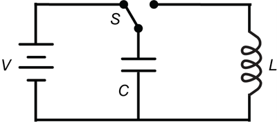
A square parallel circuit diagram containing a battery labeled V in the left branch, a capacitor labeled C in the middle branch, and an inductor labeled L in the right branch. A switch labeled S is shown in the middle branch in the left position to make a closed circuit form with the capacitor and battery in series with each other while the inductor is in an open branch. The switch is placed such that if it were in the right position, a closed circuit would form with the inductor and capacitor in series with each other, while the battery would be in an open branch.
Switch S is flipped to the left to fully charge the capacitor, C. Switch S is then flipped to the right. All circuit elements have zero internal resistance. Which of the following statements describes the resulting current flow in the inductor, L?
- A direct current flows for a finite amount of time until the capacitor is completely discharged.
- An alternating current flows for a finite amount of time until the inductor dissipates the energy as heat.
- An alternating current with a constant frequency flows indefinitely.
- A constant direct current flows indefinitely.
Correct Response and Explanation (Show Correct ResponseHide Correct Response)
C. The resulting electric current flow in an LC series circuit depends on the capacitance and inductance of the circuit and will alternate at a specific frequency. Before the switch is flipped, the inductor is not part of the circuit, and the capacitor is fully charged by the battery. After the switch is flipped, the capacitor begins to discharge, providing current to the right loop of the circuit that is now in series with the inductor. The discharge of the capacitor will drive a current through the inductor, building up a magnetic field around the inductor. The voltage across the capacitor falls to zero as the charge is used up by the current flow. Then the inductor's magnetic field induces a voltage in the coil since inductors oppose changes in current. This induced voltage causes a current to begin to recharge the capacitor with a voltage of opposite polarity to its original charge. This creates a feedback loop of current in the circuit such that the capacitor charges and discharges with cycles of opposite polarity. The result is in an alternating current whose frequency can be determined by the capacitance and inductance values.

 View Cart